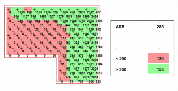

Each grid point on the floor plan denotes a square area of space that is analyzed to determine the amount of %sDA or %ASE it achieves. Seeing the grid size validates the accuracy of the simulation. This means the simulation is more accurate. Pixelation is a direct result of the design of the sDA/ASE calculation method. NOTE: SHGC and U-Value for Glazing materials can be changed on the Baseline Energy Page. A higher VT% means more daylight penetrates the interior space which, can directly impact electric lighting and its associated cooling loads. Using the Visible Transmittance (VT%) slider, users can control the amount of daylight that passes through their windows. Visual Transmittance (VT%): Visible transmittance is the amount of light in the visible spectrum that passes through a glazing material. There is only a slight change in accuracy between grid sizes so if you want a fast idea the larger grid size is perfectly acceptable for early stage decisions. We autoruns at a 6 ft grid but can be modified by the user down to 2 ft for a LEED level daylight grid. The smaller the grid size, the slower the simulation. Grid Size: The grid size as a measurement unit in ft/m represents the size of the analysis grid on which the simulation is done. The geometry is then accurately represented within the web-app. Important: To represent trees upload boxes instead of complex foliage. The geometry is pulled out in various layers for glass surface, wall surfaces, floor surfaces, roof surfaces, shading structures (which can include overhang, fins, light-shelves, and site context).

Geometry: we pull in the Geometry directly from your 3D model using the cove.tool plugins for Revit, Rhino/Grasshopper, and Sketchup. This input generates site context needed to accurately replicate the conditions of your project.

In cove.tool, this is done automatically for you as soon as you enter a building location. Location: The sky dome, which represents the amount of light that emanates from the sun, the sky, and clouds, is auto-created and loaded for any location on Earth. How does it set up the model? In a daylight model, there are a few factors that are key to determining the impact of daylight on your building including: 1. This is also the correct settings for a LEED daylight analysis. This allows any user to construct a realistic simulation and avoids "cheating" the simulation with incorrect inputs. To speed up the simulation we keep the reflectivity percentages (materiality) fixed with the following assumptions: Floors 20%, Interior Walls 50%, Ceiling/Roof 70%, Exterior Façade (shading devices, mullions, light shelves, etc.) 50%, and exterior Walls 35%, Outside Ground 40%. We use a 3 phase method for maximum accuracy that compares with a 6 bounce method in Radiance. Environmental conditions are based on the Tregenza sky constructed from the weather file with 576 subdivisions.


 0 kommentar(er)
